Modbus RTU Module
This Lua module extends the Barracuda App Server Modbus TCP client so it can communicate over Modbus RTU on serial links such as RS-232 and RS-485. In practice, the module acts as a transport adapter: it keeps the familiar Modbus client API while using the UART API for the underlying serial communication.
Note
The module is currently included in the Xedge32 firmware, but it may be moved into a separately distributed Lua module in a future release.
Creating an RTU Client
Function signature:
rtu = require"modbus.rtu".connect(port, config)
Parameters
The port and config arguments are forwarded to Creating a UART Object. The
config table also supports the Modbus TCP client’s ``onclose` option
<https://realtimelogic.com/ba/doc/?url=Modbus.html#onclose>`_.
Return Value
The function returns a Modbus object with the same method set as the Modbus TCP client.
The returned object is preconfigured for asynchronous cosocket operation, which means you should provide a callback for each Modbus operation.
Basic Example
local cfg = {
   baudrate = 9600,
   txpin = 42,
   rxpin = 41,
   onclose = function(err)
      trace("Serial Comm. Err.", err)
   end
}

-- Does not return errors, but may throw on incorrect settings
local mb = require"modbus.rtu".connect(1, cfg)

local function mycallback(data, err, transaction, client)
   trace("table" == type(data) and ba.json.encode(data) or data, err)
end

local unitId = 1
mb:wholding(0, {1,2,3,4,5,6,7,8,9,10,11,12,13,14,15,16,17,18,19,20}, unitId, mycallback)
mb:rholding(0, 20, unitId, mycallback)
The callback above prints results similar to:
true  nil
[1,2,3,4,5,6,7,8,9,10,11,12,13,14,15,16,17,18,19,20]  nil
RS-232, Full-Duplex RS-485, and Half-Duplex RS-485
The first example configures the UART for RS-232 or full-duplex RS-485.
For half-duplex two-wire RS-485, you also need collision-detection support and
a suitable transceiver such as ADM483 wired to the RTS GPIO pin. In that case,
enable the UART rs485 option:
local cfg = {
   baudrate = 9600,
   txpin = 42,
   rxpin = 41,
   rtspin = 40,
   rs485 = true
}
Modbus Test Bench
The image below shows a simple two-wire RS-485 test setup.
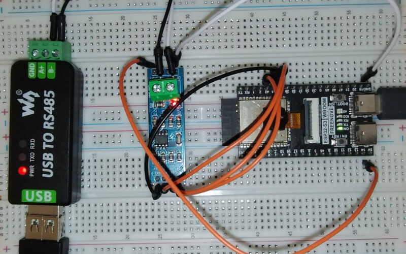
Test Bench Components
ESP32-S3
ANMBEST MAX485 RS485 transceiver module
USB-to-RS485 converter
A Modbus slave simulator running on Windows and connected to the converter
Wiring Example
The following wiring matches the half-duplex configuration shown earlier.
Power connections:
VCC on MAX485 to 5V on the ESP32
GND on MAX485 to GND on the ESP32
Data connections:
DI on MAX485 to GPIO 42 on the ESP32 for TX
RO on MAX485 to GPIO 41 on the ESP32 for RX
Control pin:
RE and DE connected together, then wired to GPIO 40 for RTS
RS-485 bus terminals:
A and B on the MAX485 to the matching A and B lines on the USB-to-RS485 converter
For longer RS-485 wiring, also consider termination and biasing. Short bench tests may work without them, but production wiring should follow normal RS-485 bus design rules.
Practical Guidance
Use RS-232 or full-duplex RS-485 when the wiring and hardware already support separate send and receive paths.
Use half-duplex RS-485 when you need a multidrop industrial bus, but make sure your transceiver and RTS wiring are configured correctly.
Keep the callback-based programming style from the Modbus client API; the RTU transport layer is designed around asynchronous requests and responses.
If requests time out, first verify baud rate, parity, slave unit ID, A/B polarity, and shared ground before changing the Lua code.