PWM API
The PWM API is built on top of the ESP-IDF LEDC peripheral. Although LEDC was originally designed for LED dimming, it is also a general-purpose PWM engine that works well for tasks such as:
LED brightness control,
RGB color mixing,
simple tone generation,
fan and motor control interfaces, and
hobby servo signaling.
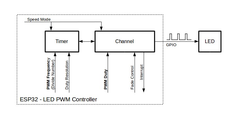
The ESP32 LEDC peripheral provides 16 channels that can generate independent waveforms. These channels are divided into two groups of eight. One group runs in high-speed mode, where duty updates are handled fully in hardware. The other group runs in low-speed mode. For background information, see the ESP-IDF LEDC documentation.
Typical PWM Workflow
Using PWM in Xedge32 normally follows three steps:
Configure a timer with
esp32.pwmtimer().Open one or more output channels with
esp32.pwmchannel().Change the duty cycle with
channel:duty()or perform hardware-driven transitions withchannel:fade().
The timer controls the shared timing: frequency and duty resolution. The channel controls the actual output pin and duty value. Several channels can use the same timer when they should run at the same frequency.
Quick Start Example
The example below configures timer 0, opens channel 0 on GPIO 18, drives the output at full duty cycle for two seconds, then turns it off again.
local ok, err = esp32.pwmtimer{
   mode = "LOW",
   bits = 13,
   timer = 0,
   freq = 5000,
}

if ok then
   local led, chErr = esp32.pwmchannel{
      mode = "LOW",
      timer = 0,
      channel = 0,
      gpio = 18,
      duty = 2^13 - 1,
   }

   if led then
      ba.sleep(2000)
      led:duty(0)
      led:close()
   else
      trace(chErr)
   end
else
   trace(err)
end
Creating a PWM Timer
Function signature:
ok, err = esp32.pwmtimer(config)
This function configures a timer. Call it before opening any channel that uses that timer. A given timer only needs to be configured once.
Required config fields:
mode:"LOW"or"HIGH".bits: Duty resolution in bits.timer: Timer number.freq: Output frequency in Hertz.
The duty range is determined by bits. For example, bits = 13 gives a
range from 0 to 8191. A 50 percent duty cycle is therefore roughly
4096.
Some newer ESP32 targets do not provide the same high-speed LEDC mode as the original ESP32. If high-speed mode is not available on the selected target, the firmware uses the supported low-speed mode internally.
Return values:
trueon successnil, erron failure
Creating a PWM Channel
Function signature:
channel, err = esp32.pwmchannel(config)
This function opens a channel object that is bound to a previously configured timer.
config fields:
mode: Required. Must match the mode used byesp32.pwmtimer().timer: Required. Must match the timer configured earlier.channel: Required. Channel number to use.gpio: Required. Output GPIO pin.duty: Optional initial duty cycle from0to2^bits - 1.hpoint: Optional initial hpoint value. Default is0.callback: Optional Lua callback used with hardware-supported fading.
Use a callback only when you need to know that a fade has completed. For simple
brightness or servo-position updates, channel:duty() is usually enough.
Return values:
channel object on success
nil, erroron failure
Channel Object Methods
channel:duty(pwmDutyCycle [, hpoint])
Sets the channel duty cycle immediately.
Parameters:
pwmDutyCycle: Value from0to2^bits - 1.hpoint: Optional updated hpoint value.
Use this method when you want direct, immediate control over the output level.
channel:fade(pwmDutyCycle, time)
Uses the hardware fade engine to transition from the current duty cycle to a new target duty cycle.
Parameters:
pwmDutyCycle: Target duty cycle from0to2^bits - 1.time: Maximum fade duration in milliseconds.
To use fading, the channel must be created with a callback. The callback is invoked when the fade operation completes.
channel:close()
Releases the PWM channel and the resources associated with it. Closing a channel also stops its output.
Example 1: LED Fading with Callback
This example demonstrates interrupt-driven fading. The callback is invoked when each fade completes, and it starts the next fade in the opposite direction.
local bits = 13
local maxPwmDuty = 2^bits - 1

local ok, err = esp32.pwmtimer{
   mode = "HIGH",
   bits = bits,
   timer = 0,
   freq = 5000,
}

if ok then
   local duty, led = 0, 0

   local function callback()
      trace("led callback triggered", duty)
      duty = duty == 0 and maxPwmDuty or 0
      led:fade(duty, 1000)
   end

   led, err = esp32.pwmchannel{
      callback = callback,
      mode = "HIGH",
      channel = 0,
      timer = 0,
      gpio = 18,
   }

   if led then
      callback()
   else
      trace(err)
   end
else
   trace(err)
end
Why this pattern is useful:
It keeps the animation logic in Lua.
It lets the hardware perform the actual ramp.
It avoids manually updating duty cycle values in a timer loop.
Example 2: Servo Sweep
The next example uses PWM to move a hobby servo between two end positions. It follows the same callback-driven pattern as the LED example, but uses a 50 Hz timer and duty-cycle values chosen for a typical 0 to 180 degree servo range.
local ok, err = esp32.pwmtimer{
   mode = "LOW",
   bits = 13,
   timer = 0,
   freq = 50,
}

if ok then
   local minServoDuty, maxServoDuty = 409, 819
   local duty = maxServoDuty
   local servo

   local function callback()
      trace("servo callback triggered", duty)
      duty = duty == minServoDuty and maxServoDuty or minServoDuty
      servo:fade(duty, 3000)
   end

   servo, err = esp32.pwmchannel{
      callback = callback,
      mode = "LOW",
      channel = 0,
      timer = 0,
      gpio = 14,
   }

   if servo then
      callback()
   else
      trace(err)
   end
else
   trace(err)
end
The two duty values in this example were derived from the
calculatePwmDutyCycle() logic used in the servo.lsp example.
Important Runtime Note
If you place a callback-driven PWM example in an LSP page, remember that the Lua object can be garbage-collected after the page finishes executing if no reference is kept alive. That is convenient during quick experiments, but in a real application you normally store the PWM object somewhere persistent.
Practical Guidance
Use high-speed mode when you want the cleanest hardware-driven duty-cycle updates.
Use low-speed mode when that matches your application or existing design.
Choose the timer
bitsvalue based on the balance you need between duty resolution and frequency.Use
channel:duty()for immediate updates andchannel:fade()when you want hardware-assisted transitions without building your own timer loop.For motors and LED strips, use the proper driver hardware. A GPIO/PWM pin is a control signal, not a power output.