RMT API
The ESP32 RMT peripheral, short for Remote Control, is a timing-oriented signal engine that can both transmit and receive precisely timed digital pulse sequences. It was originally introduced for infrared remote-control protocols, but it is far more general than the name suggests.
In practice, the RMT peripheral is a very useful tool whenever a protocol is defined in terms of pulse widths rather than bytes on a conventional bus. This makes it a strong fit for:
infrared protocols,
1-wire devices,
addressable LED strips such as WS2812B,
custom pulse-encoded signaling,
pulse measurement and decoding tasks, and
other applications where sub-microsecond timing matters.
Because the peripheral handles timing in hardware, it is often a better choice than trying to generate or measure pulse trains directly from Lua.
For beginners, the easiest way to decide whether RMT is the right API is to ask whether the protocol is described by pulse widths. If the device talks in bytes, try UART, I2C, or another bus first. If the device talks in high/low timings, RMT is usually the correct tool.
Application Examples
Two especially common uses for RMT in Xedge32 projects are:
1-wire communication Timing is critical in 1-wire protocols, and RMT provides the precision needed for reliable reads and writes.
Addressable LED strips LED strips such as WS2812B require very specific pulse timing. RMT lets you generate those waveforms in hardware instead of bit-banging them from Lua.
RMT Symbol Layout
The RMT hardware represents a waveform as a sequence of RMT symbols. Each symbol contains timing and logic-level information describing two consecutive pulse segments.
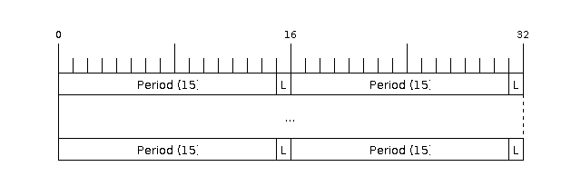
Bit fields in an RMT symbol as defined by the hardware.
Each RMT symbol contains:
a duration value for the first segment,
a logic level for the first segment,
a duration value for the second segment, and
a logic level for the second segment.
Duration values are expressed in RMT clock ticks, not in seconds directly. The tick duration depends on the configured channel resolution.
Understanding Tick Resolution
The configured resolution determines how to interpret durations:
at
1,000,000Hz, one tick is1 us,at
10,000,000Hz, one tick is0.1 us,at
80,000,000Hz, one tick is12.5 ns.
This is one of the most important ideas when working with RMT. The symbol data does not store human-friendly time units. It stores counts that are meaningful only when combined with the selected resolution.
Lua RMT Symbol Representation
In Lua, a single RMT symbol is represented as a four-element table:
{ level0, duration0, level1, duration1 }
Example:
{
   1, 350, 0, 800
}
If the channel resolution is 1 MHz, the symbol above means:
drive the line high for
350 us,then drive it low for
800 us.
This table format is compact, but it is helpful to think of it as a small waveform fragment rather than as generic numeric data.
Lua RMT Byte Encoding
Many pulse protocols define how each data bit is encoded as a pair of pulses. For example:
a binary
0might be sent as a short-high then long-low pulse pair,a binary
1might be sent as a long-high then short-low pulse pair.
Xedge32 supports a convenient Lua structure for describing this pattern at the byte level:
{
   booleanMsbFirst,
   symbolForBit0,
   symbolForBit1,
   { byteArray }
}
Fields:
booleanMsbFirst:trueto transmit the most-significant bit first,falsefor least-significant-bit first.symbolForBit0: RMT symbol that represents a transmitted zero bit.symbolForBit1: RMT symbol that represents a transmitted one bit.{ byteArray }: Array of bytes to encode and transmit.
Example at 10 MHz resolution:
{
   true,
   {1, 4, 0, 8},
   {1, 8, 0, 4},
   {0x00, 0x55, 0xFF}
}
With a resolution of 10,000,000 Hz, the values 4 and 8 correspond
to 0.4 us and 0.8 us respectively.
RMT TX API
Creating a TX Channel
Function signature:
rmttx, err = esp32.rmttx(cfg [, rx])
This function creates a transmit channel object. The channel starts out
disabled, so you must call rmttx:enable() before transmitting.
The optional rx argument lets you pair a TX and RX channel on the same GPIO
so they can cooperate on a bidirectional bus such as 1-wire.
TX Configuration Options
Required fields:
gpio: Output GPIO pin.resolution: Tick resolution in Hertz.
Optional fields:
mem: Memory or DMA buffer sizing. Default is64.queue: Transaction queue depth. Default is4.invert: Invert the outgoing logic level. Default isfalse.dma: Enable DMA backend. Default isfalse.opendrain: Configure the GPIO in open-drain mode. Default isfalse.callback: Function called when transmission completes.
Optional carrier modulation fields:
dutycycle: Carrier duty cycle.frequency: Carrier frequency in Hertz. Maximum is80000000.polaritylow: Select the logic level on which the carrier is applied.
TX Object Methods
rmttx:enable()
Enables the RMT TX channel and prepares it for transmission.
rmttx:disable()
Disables the TX channel and stops further activity. This is especially useful for transmissions that were started in loop mode.
rmttx:transmit(cfg, symbols)
Queues or starts transmission of one or more RMT symbols.
Parameters:
cfg: Transmission options.symbols: Either an array of direct RMT symbols or one or more byte-encode structures as described earlier.
Supported cfg fields:
loop: Number of repeat loops. Use-1for infinite looping.eot: Output level to hold at end of transmission.
rmttx:close()
Closes the TX channel and releases its resources.
TX Example 1: Musical Score
The following example plays a simple melody, Beethoven’s Ode to Joy, by transmitting a square wave for each note frequency. The score table is adapted from Espressif’s musical buzzer example.
local score = {
   {740, 400}, {740, 600}, {784, 400}, {880, 400},
   {880, 400}, {784, 400}, {740, 400}, {659, 400},
   {587, 400}, {587, 400}, {659, 400}, {740, 400},
   {740, 400}, {740, 200}, {659, 200}, {659, 800},

   {740, 400}, {740, 600}, {784, 400}, {880, 400},
   {880, 400}, {784, 400}, {740, 400}, {659, 400},
   {587, 400}, {587, 400}, {659, 400}, {740, 400},
   {659, 400}, {659, 200}, {587, 200}, {587, 800},

   {659, 400}, {659, 400}, {740, 400}, {587, 400},
   {659, 400}, {740, 200}, {784, 200}, {740, 400}, {587, 400},
   {659, 400}, {740, 200}, {784, 200}, {740, 400}, {659, 400},
   {587, 400}, {659, 400}, {440, 400}, {440, 400},

   {740, 400}, {740, 600}, {784, 400}, {880, 400},
   {880, 400}, {784, 400}, {740, 400}, {659, 400},
   {587, 400}, {587, 400}, {659, 400}, {740, 400},
   {659, 400}, {659, 200}, {587, 200}, {587, 800},
}

local resolution = 1000000

local function play(rmt)
   for _, note in ipairs(score) do
      local freq, duration = note[1], note[2]
      local symbolDuration = resolution / freq / 2
      rmt:transmit({loop = duration * freq / 1000}, {
         {0, symbolDuration, 1, symbolDuration}
      })
      coroutine.yield()
   end
   rmt:close()
end

local coro = coroutine.create(play)

local rmt, err = esp32.rmttx{
   gpio = 0,
   resolution = resolution,
   callback = function()
      coroutine.resume(coro)
   end
}

if rmt then
   rmt:enable()
   coroutine.resume(coro, rmt)
else
   trace(err)
end

function onunload()
   rmt:close()
end
How the Musical Example Works
The play() function runs as a Lua coroutine. That lets the code look
sequential even though the actual note timing is event-driven.
For each note:
The frequency is converted into a half-period duration.
A single RMT symbol is transmitted in a loop to generate a square wave.
The coroutine yields.
The TX callback resumes the coroutine after the note duration finishes.
This is a useful general RMT pattern: let hardware perform the timing while Lua coordinates higher-level sequencing.
TX Example 2: WS2812B LED Strip
The following example drives a WS2812B-compatible LED strip by defining the
timing for bit 0 and bit 1 and then repeatedly retransmitting updated
color data.
local leds = 1
local gpioPin = 48
local rmt, err

local data = {}
for i = 1, leds * 3 do
   table.insert(data, ba.rnd(0, 0xFF))
end

local function transmit()
   rmt:transmit({}, {
      {
         true,
         {1, 4, 0, 8},
         {1, 8, 0, 4},
         data
      },
      {0, 150, 0, 150}
   })
end

rmt, err = esp32.rmttx{
   gpio = gpioPin,
   resolution = 10000000,
   callback = function()
      for i = 1, #data do
         local c = data[i] + 1
         if c > 0xFF then
            c = 0
         end
         data[i] = c
      end
      transmit()
   end
}

if rmt then
   rmt:enable()
   transmit()
else
   trace(err)
end

function onunload()
   trace"Stopping wled"
   if rmt then
      for i = 1, #data do
         data[i] = 0
      end
      transmit()
      transmit = function()
         rmt:close()
      end
   end
end
Breaking Down the LED Example
Preparing color data:
datacontains three bytes per LED.Each group of three bytes represents one RGB color value.
Transmit function:
The first item in the transmit table describes byte encoding for the LED protocol.
trueselects MSB-first transmission.{1, 4, 0, 8}defines the waveform for a zero bit.{1, 8, 0, 4}defines the waveform for a one bit.{0, 150, 0, 150}adds the reset pulse after the color data.
Continuous animation:
The TX callback updates the color table after each completed transfer.
The callback then starts the next frame.
This creates a continuous animation loop without a separate timer.
Cleanup:
onunload()turns the LEDs off before closing the channel.This matters when the code runs as an
.xluapage and may be reloaded or stopped while the previous transmission is still active.
RMT RX API
Creating an RX Channel
Function signature:
rmtrx, err = esp32.rmtrx(cfg)
This creates a receive channel that captures incoming pulse timings as RMT symbols.
RX Configuration Options
Required fields:
gpio: Input GPIO pin.resolution: Tick resolution in Hertz.callback: Lua function called when a receive job completes.
Optional fields:
mem: Memory or DMA buffer sizing. Default is64.invert: Invert input levels before processing. Default isfalse.dma: Enable DMA backend. Default isfalse.
RX callback signature:
function callback(symbols, overflow)
Arguments:
symbols: Array of received RMT symbols.overflow: Boolean indicating whether the receive buffer overflowed.
RX Object Methods
rmtrx:receive(cfg)
Starts a receive job and returns immediately.
Receive cfg fields:
min: Minimum valid pulse duration in nanoseconds. Shorter pulses are treated as glitches.max: Maximum valid pulse duration in nanoseconds. Longer pulses are treated as a stop signal and end the receive operation.len: Optional receive buffer length in RMT symbols. Default is512.defer: Optional boolean. Relevant when TX and RX are linked to the same GPIO.
When defer is used with a linked TX/RX pair:
falsemeans reception starts immediately, so transmitted symbols may also appear in the receive result.truedelays reception until the linked TX channel finishes transmitting.
rmtrx:close()
Closes the RX channel and releases its resources.
RX Example: 1-Wire Temperature Read
The following example shows how RMT can be used to implement a 1-wire temperature transaction against a DS18B20-style sensor.
 1local tInsert = table.insert
 2local cResume, cYield = coroutine.resume, coroutine.yield
 3
 4local function decodeBytes(symbols)
 5   local mask, byte, t = 1, 0, {}
 6   for _, sym in ipairs(symbols) do
 7      if sym[2] <= 15 then
 8         byte = byte | mask
 9      end
10      mask = mask << 1
11      if 256 == mask then
12         tInsert(t, byte)
13         mask, byte = 1, 0
14      end
15   end
16   return t
17end
18
19local function readTemp(gpio, callback)
20   local coro
21
22   local function tempThread()
23      local txCfg = {eot = 1}
24
25      local rx <close> = esp32.rmtrx{
26         gpio = gpio,
27         resolution = 1000000,
28         callback = function(symbols)
29            cResume(coro, symbols)
30         end
31      }
32
33      local tx <close> = esp32.rmttx({
34         gpio = gpio,
35         opendrain = true,
36         resolution = 1000000,
37      }, rx)
38
39      local function busReset()
40         rx:receive{min = 2000, max = 480 * 2 * 1000}
41         tx:transmit(txCfg, {{0, 480, 1, 70}})
42         local symbols = cYield()
43         if #symbols < 2 then
44            callback(nil, "No sensors connected")
45         end
46         return #symbols < 2
47      end
48
49      local function sendCommand(cmd)
50         rx:receive{min = 900, max = 70 * 1000}
51         tx:transmit(txCfg, {
52            {
53               false,
54               {0, 60, 1, 2},
55               {0, 6, 1, 56},
56               cmd
57            }
58         })
59         return cYield()
60      end
61
62      local function readBytes(len)
63         local t = {}
64         for i = 1, len do
65            tInsert(t, 0xFF)
66         end
67         return sendCommand(t)
68      end
69
70      tx:enable()
71      tx:transmit(txCfg, {{1, 1, 1, 0}})
72      if busReset() then
73         return
74      end
75
76      sendCommand{0xCC, 0x44}
77      ba.timer(function()
78         cResume(coro)
79      end):set(1000, true)
80      cYield()
81
82      if busReset() then
83         return
84      end
85
86      sendCommand{0xCC, 0xBE}
87      local data = decodeBytes(readBytes(2))
88      local raw = (data[2] << 8) + data[1]
89      callback(raw * 0.0625)
90   end
91
92   coro = coroutine.create(tempThread)
93   cResume(coro)
94end
95
96readTemp(1, function(temp, err)
97   trace(temp, err)
98end)
Understanding the 1-Wire Example
This example is dense, so it helps to break it into pieces.
1-wire background:
A bus reset begins communication by pulling the line low for at least
480 us.A device indicates presence by pulling the line low in response.
Bit timing determines whether the transmitted or received value is a zero or a one.
How the Lua code is organized:
tempThread()is written as a coroutine so the protocol can be expressed in sequential steps.The RX callback resumes the coroutine whenever a receive operation completes.
TX and RX share the same GPIO pin, which is required for 1-wire signaling.
What decodeBytes() does:
It examines the low-duration part of each received symbol.
Short low pulses are interpreted as binary
1.Longer low pulses are interpreted as binary
0.Bits are shifted into bytes in least-significant-bit-first order.
Protocol flow:
Reset the bus.
Send
0xCCand0x44to skip ROM selection and start temperature conversion.Wait for the conversion to complete.
Reset the bus again.
Send
0xCCand0xBEto read the scratchpad.Decode the returned bytes into a temperature value.
Why the example uses 0xFF during reads:
In 1-wire, the master must still generate timing slots while reading. Sending a series of one bits creates those read slots, and the sensor alters the observed pulse widths to encode its response.
Garbage-Collection Consideration
One subtle issue in coroutine-driven code like this is object lifetime. The example intentionally keeps the logic focused on protocol flow, but a production implementation should keep an explicit reference to the coroutine or wrap the entire behavior in a long-lived object.
Without a stable reference, Lua’s garbage collector could reclaim the coroutine while it is waiting for an event. If that happened, the callback would never resume the protocol.
Practical Guidance
Start by choosing a resolution that makes your protocol timing easy to reason about.
Use direct symbols when you are hand-crafting pulse sequences.
Use byte encoding when the protocol naturally describes timing for bit
0and bit1.Pair TX and RX channels on the same GPIO for bidirectional single-wire buses.
Always think about cleanup and object lifetime when running long-lived RMT activity from LSP or hot-reloaded code.
If your timing values are hard to read, lower the resolution so common pulse widths convert to simple integer tick counts.